

RADBAR / APPLICATION ENGINEERING
Industrial & built environments
Plan panels, access points and transparent windows as an integrated enclosure, with validation under the actual equipment operating conditions.
 AI-generated application illustration
Make shielding part of the design.
Plan panels, access points and transparent windows as an integrated enclosure, with validation under the actual equipment operating conditions.
How do you shield an X-ray inspection room or imaging space?
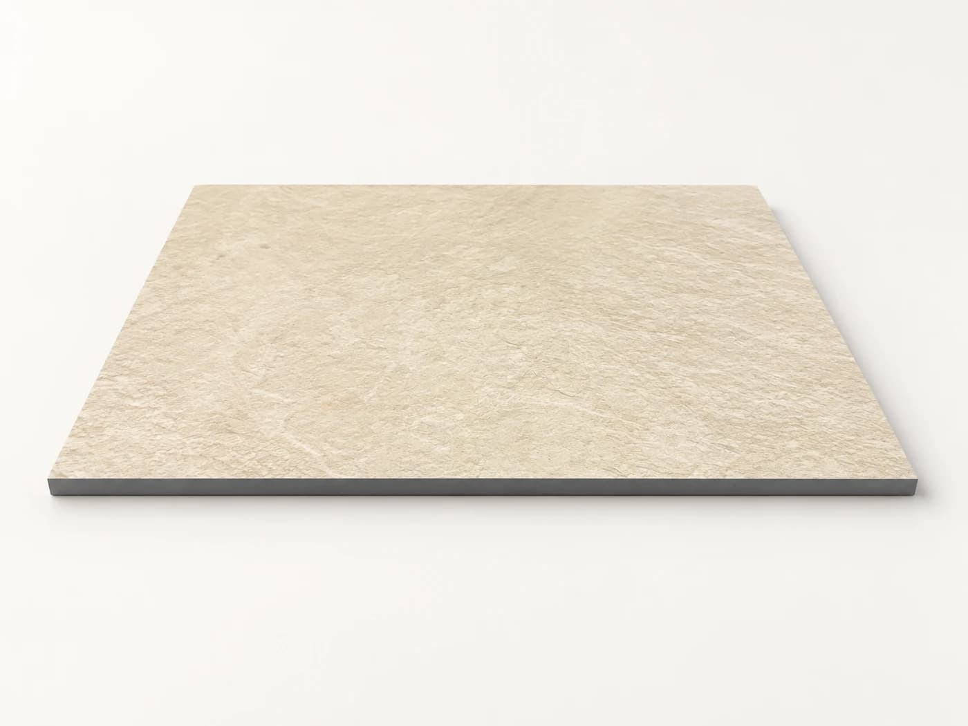
Shielding for industrial inspection rooms and imaging spaces should be designed as a complete enclosure of walls, doors, viewing windows, penetrations and access points. The Radbar catalog lists lead-free composite wall panels NFPb200-1 and NFPb200-2 (2440 × 1220 mm, 6 or 10 mm thick, 2 mmPb as listed, 25 or 37 kg/m²) and lead-containing clear acrylic (0.07–0.5 mmPb) for viewing windows. A single panel rating does not define the protection of a room.
Reviewed 2026-09-24 · values from the model catalogs and editions cited
HOW IT FITS TOGETHER
See where the protection works.
Shielding a room as a complete enclosure
- Wall panels form the main barrier; each wall’s requirement comes from the shielding design.
- Joints and corners must keep shielding continuous.
- Door and frame are a separate path and need their own detail.
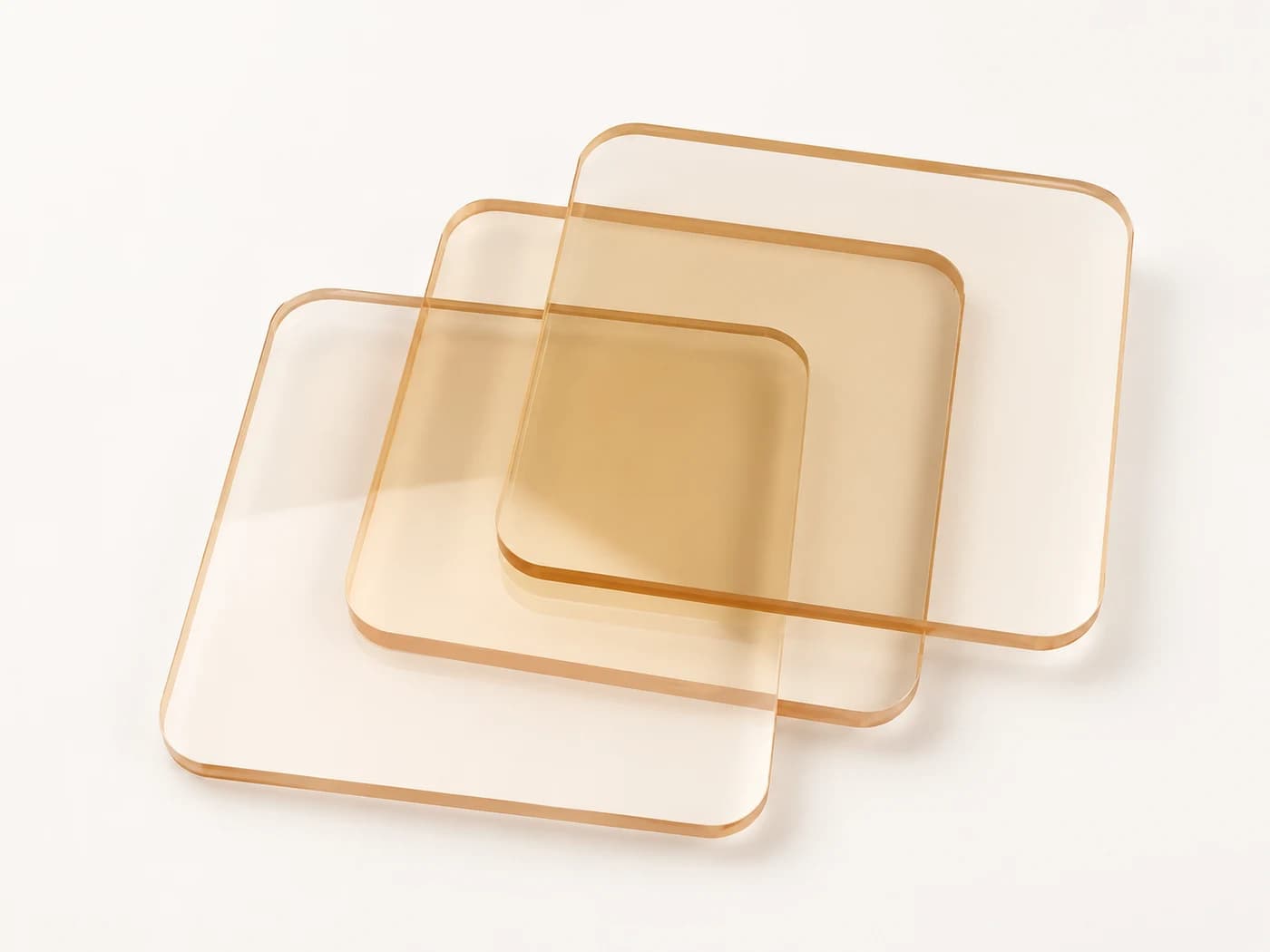
- Viewing window in clear lead acrylic (a lead-containing material).
- Pipe and cable penetrations need shielding details.
- Source position and workload define the protection each wall needs.
FROM THE ORIGINAL PRODUCT LITERATURE
Catalog data, with its conditions.
| Model | Size / thickness | Lead equivalence (mmPb) | Areal weight (kg/m²) | Material |
|---|---|---|---|---|
| NFPb200-1 | 2440 × 1220 × 6 mm | 2 | 25 | Lead-free |
| NFPb200-2 | 2440 × 1220 × 10 mm | 2 | 37 | Lead-free |
| Clear lead acrylic C-2 to C-12 | 600 × 800 / 1000 × 1200 mm; 2–12 mm | 0.07–0.5 | 3.2–19 | Lead-containing |
Panel sheet weights are listed as 77 and 110 kg; sheet and areal weights do not reconcile exactly, so confirm shipped mass. Beam conditions for the listed 2 mmPb require the corresponding report.
Source: Wall panel p.1; Clear lead acrylic 2509 p.2
- Panels combine rare-earth shielding components with a flame-retardant polymer and a decorative face: dark walnut, light walnut or light oak.
- Installation by adhesive or clip-on fixing over a substrate; design frames and fasteners for the actual panel weight.
- Clear lead acrylic can be cut, drilled and machined; light transmission ranges from 93% (C-2) to 87% (C-12).
SELECTION STEPS
Make the decision in order.
- 01
Start from the shielding design
Source characteristics, workload and position define the required protection for each wall.
- 02
Coordinate before layouts are fixed
Align structural loads, panel joints, access and services with the shielding design before cutting.
- 03
Keep details continuous
Plan corners, joints, door frames, penetrations and access panels so shielding is not interrupted.
- 04
Specify viewing windows
Choose the acrylic grade from clear aperture, edge support, optical needs and beam conditions.
- 05
Validate the installed room
Test the complete construction under actual equipment operating conditions.
COMMON MISTAKES
Where specifications usually go wrong.
- Using one panel rating to describe the protection of an entire room.
- Underestimating handling and framing loads of 77–110 kg sheets.
- Specifying lead acrylic as a lead-free window.
- Applying the panels to nuclear or radiotherapy rooms without a source-specific engineering assessment.
Related products & materials
Questions worth asking.
Can a panel rating define the protection of an entire room?
No. Joints, doors, viewing windows, penetrations, source position and workload all affect the enclosure. Assess the complete installed structure under the actual operating conditions.
When should shielding be considered in construction design?
Before finalizing wall layouts and openings. Coordinate structural loads, panel joints, access and services with the shielding design before cutting and installation.
LET’S ENGINEER WHAT’S NEXT
Your application. Our next conversation.
Share your equipment, radiation conditions and design constraints. Start with a material decision grounded in evidence.