

Lead-free composite shielding
Lead-free composite systems provide X-ray attenuation and form the protective structure. Lead equivalence is listed per material type and test condition; see the table below.
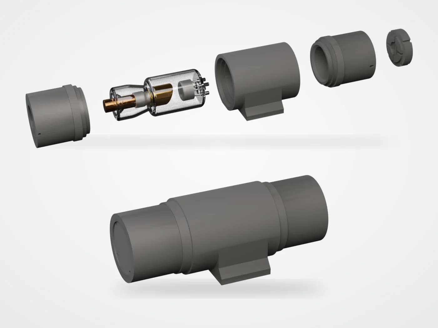 Rendering based on product reference
RADBAR / MATERIALS
Compression-moulded lead-free composite sleeves that fit over X-ray tube assemblies to attenuate scatter and leakage radiation while providing electrical insulation and mechanical protection. Rigid epoxy, flexible silicone and two-component cast types are designed around the customer’s tube model.
Lead-free materialOEM componentsElectrical insulationSource: manufacturer product literature linked above. Confirm current model, test conditions and supply specification for your order.
The 2026 datasheet describes sleeves moulded from lead-free composites and fitted over X-ray tube assemblies. One component combines radiation shielding, electrical insulation and mechanical protection: it attenuates scatter and leakage radiation, and a tapered side window can be shaped for the required beam direction. Material type, wall thickness and geometry are defined for each customer tube model.
Lead-free composite systems provide X-ray attenuation and form the protective structure. Lead equivalence is listed per material type and test condition; see the table below.
Designed for the high-voltage environment around the tube, the datasheet lists AC/DC 20 kV insulation, and the epoxy type has a dielectric strength of 6–10.5 kV/mm. Creepage distances and the complete insulation design still need to be verified for the assembly.
A tapered, flared side window is designed around the required output direction, so the sleeve shields leakage without obstructing the useful beam.
Profile, dimensions, wall thickness, window geometry, mounting holes and locating features are customizable. Typical process: powder pretreatment, compounding, preforming, mould charging, compression moulding, heat curing and post-processing.
Transcribed from manufacturer literature, with source references and conditions kept alongside each table.
| Type | Typical tube voltage | Key characteristics | Typical applications |
|---|---|---|---|
| Rigid epoxy | 160 kV | Good dimensional stability; high-temperature, oil and ageing resistance; good electrical insulation | Large X-ray systems, oil-cooled tubes and equipment needing long-term oil immersion and thermal stability |
| Flexible silicone | 90 kV | Lightweight and flexible; good heat dissipation; high-temperature and ageing resistance; lower forming cost | Portable X-ray systems and lower-voltage equipment (typically ≤ 120 kV) where weight and flexibility matter |
| Two-component AB cure | Customer-defined | Low tooling cost; cast and cured without a conventional production mould; suits complex shapes | Complex structures, low-volume production and customer in-house manufacturing |
Typical tube voltages come from the manufacturer’s source material. Final material and operating range depend on the specific tube model and operating conditions.
Source: Lead-Free Shielding Sleeves for X-Ray Tubes, page 1 · 2026| Property | Rigid epoxy | Flexible silicone |
|---|---|---|
| Thermal conductivity | 0.8–1.0 W/(m·K) @ 70 °C | 0.35–0.5 W/(m·K) @ 300 °C |
| Thermal diffusivity | 0.3–0.5 mm²/s @ 70 °C | 0.15–0.25 mm²/s @ 300 °C |
| Specific heat capacity | 0.5–0.6 J/(g·K) @ 70 °C | 0.50–0.60 J/(g·K) @ 300 °C |
| Thermal expansion (CTE) | 30–32 ppm/K (20–60 °C) | — |
| Lead equivalence | 2.4–2.7 mmPb @ 180 kV | ≥ 2.1 mmPb at 4.5 mm thickness (70–90 kV) |
| Dielectric strength | 6.0–10.5 kV/mm | — |
| Insulating-oil swelling ratio | 0.03% (116 days) | 0.6–0.8% (ambient) |
The epoxy lead-equivalence value does not state a thickness, and the datasheets give different conditions for silicone (the English edition adds 70–90 kV). The Chinese edition gives 60 °C for the swelling test. Confirm thickness and test conditions for your design.
Source: Lead-Free Shielding Sleeves for X-Ray Tubes, page 2 · 2026Rigid epoxy suits oil-immersed or oil-cooled tubes that need dimensional and thermal stability, with a typical tube voltage of 160 kV. Flexible silicone suits lighter, portable and lower-voltage equipment (typically ≤ 120 kV). The two-component type suits complex shapes or low-volume in-house production.
No. Listed lead equivalence is a material value. Leakage radiation of the finished tube assembly must be measured against the applicable standard with the actual sleeve, window and operating conditions.
The tube model or drawing, operating voltage and current, cooling method, operating temperature, shielding and insulation targets, weight limit and estimated volume.
Manufacturer literature · referenced pages 1–2 · edition 2026
Selection notes explain the literature and do not replace model-specific instructions, test reports or project design.
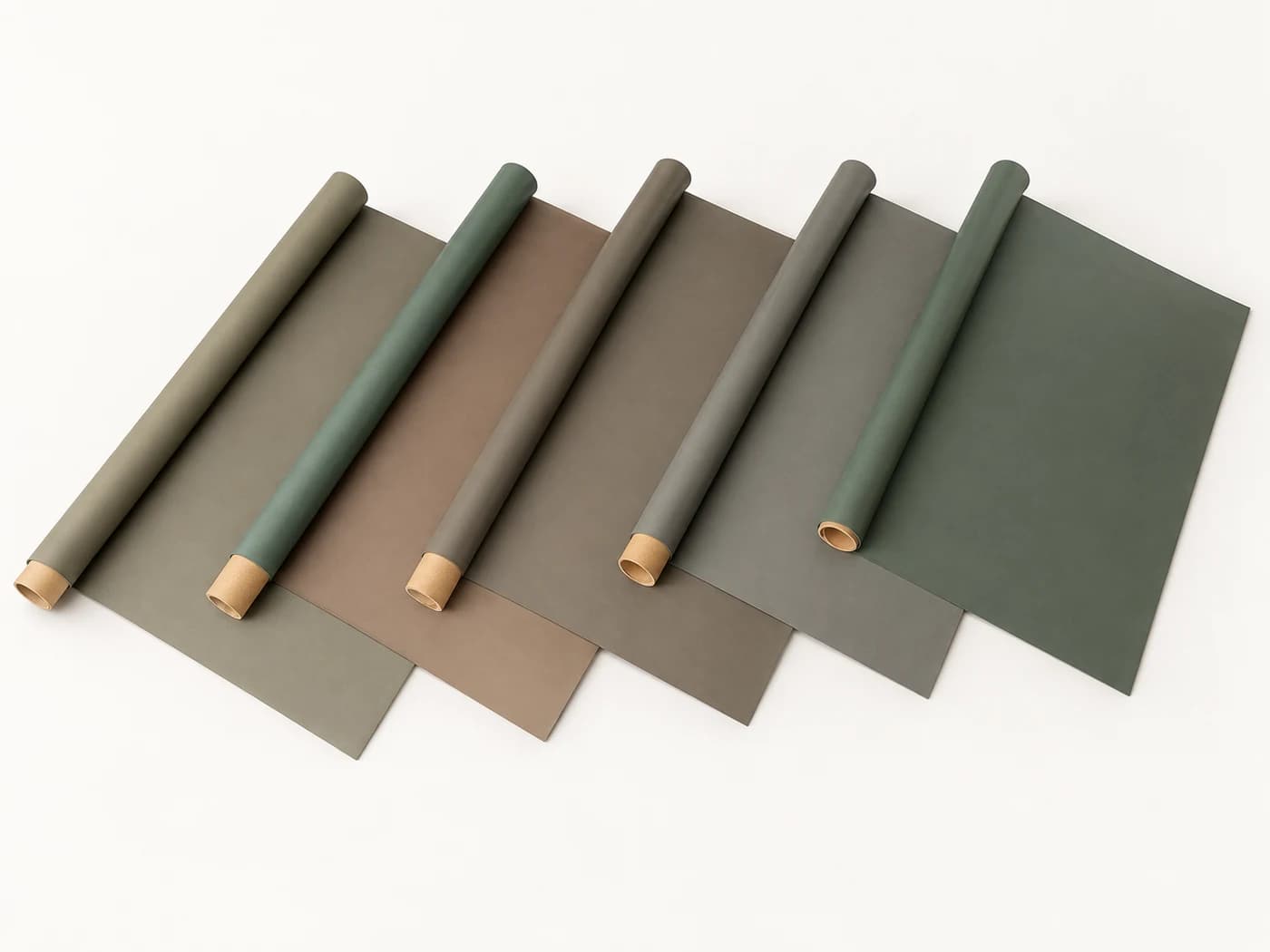 Material illustration
OEM materials / Six series
Flexible. Formable. Purpose-engineered.
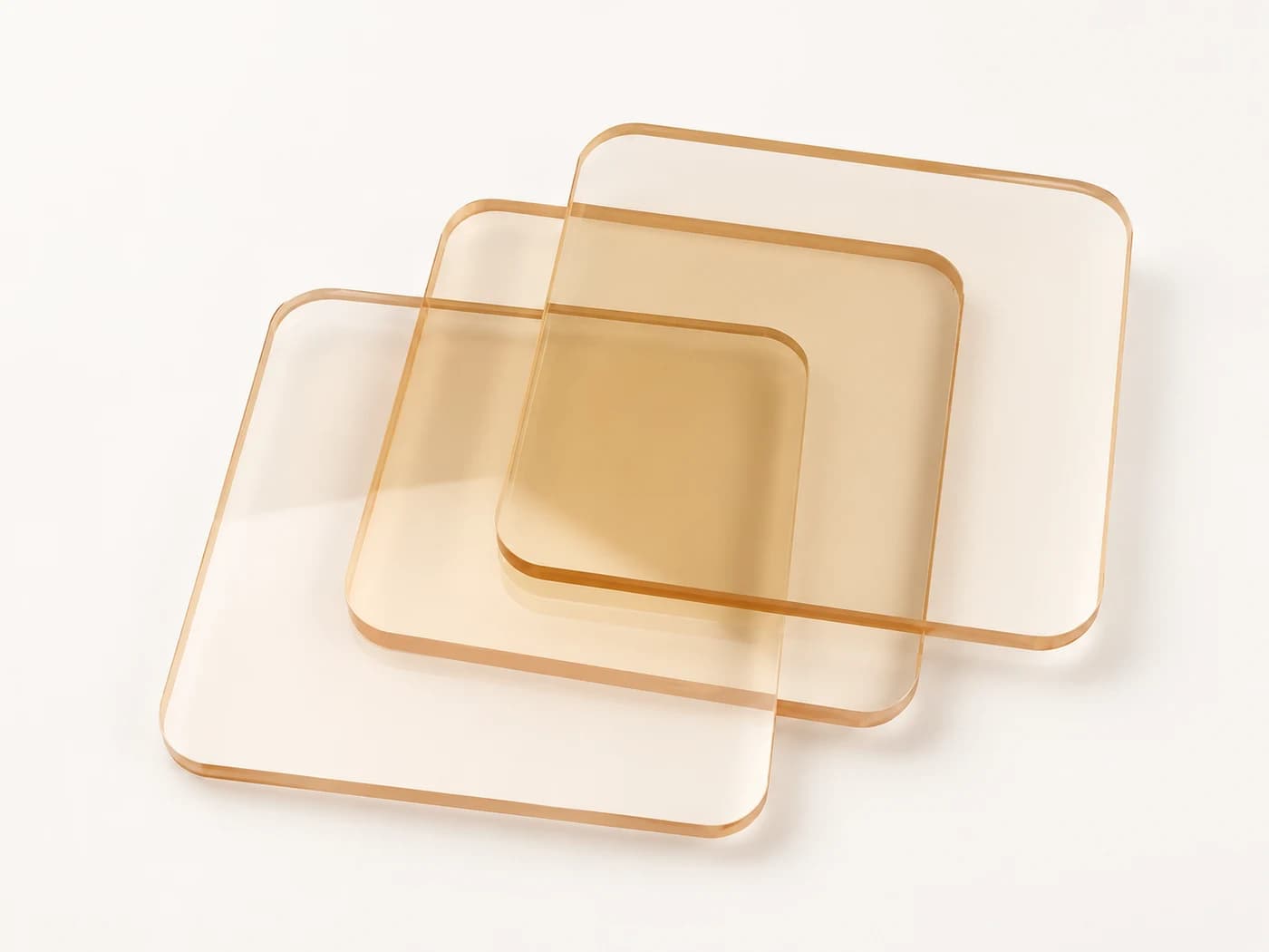 Material illustration
Optically transparent / Machinable
A clearer view of protection.
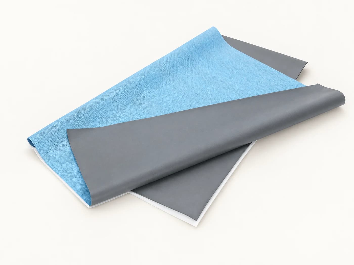 Material illustration
Single use / Custom sizes
Protection around the procedure.
LET’S ENGINEER WHAT’S NEXT
Share your equipment, radiation conditions and design constraints. Start with a material decision grounded in evidence.